
On this page
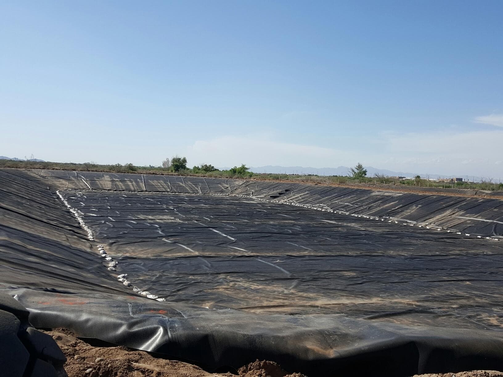
A heap leach pad liner is the engineered barrier system under a heap leach operation. In most designs it is a composite system: a geomembrane, usually 60 to 100 mil (1.5 to 2.5 mm) HDPE or LLDPE, placed over a prepared low-permeability soil layer or geosynthetic clay liner, with a drainage layer and collection piping above it. The liner does two jobs at once. It protects groundwater from process solution, and it captures metal-bearing solution so it reaches the recovery plant instead of the subgrade. Every gallon that escapes the pad is both an environmental liability and lost metal.
How heap leaching recovers metal
Heap leaching extracts metal from low-grade ore that would be uneconomic to mill. Crushed or run-of-mine ore is stacked on a lined pad in lifts, commonly 15 to 30 feet per lift, and irrigated with a leach solution. For gold and silver, that solution is dilute alkaline cyanide, typically in the range of 100 to 500 parts per million sodium cyanide at a pH around 10 to 11. For copper, it is dilute sulfuric acid at a pH near 1 to 2. As the solution percolates through the heap, it dissolves the target metal.
The metal-bearing liquid that drains from the base of the heap is called pregnant leach solution, or PLS. It flows across the liner, into a drainage network of perforated pipe set in crushed overliner material, then to lined channels and ponds, and finally to the process plant where the metal is stripped out. The stripped liquid, now barren solution, is refortified with reagent and pumped back to the top of the heap. Gold leach cycles commonly run 30 to 90 days per lift; copper heaps can leach for months to years. The whole circuit only works if the pad floor is tight, because the liner is simultaneously the floor of the reactor and the roof of the aquifer protection system.
Why the liner is the critical containment layer
Regulators treat the geomembrane as the primary engineered control between process chemistry and groundwater. Nevada, the center of North American heap leaching, permits these facilities under a zero-discharge standard (Nevada Administrative Code 445A): process components must be designed so solution is not released to the waters of the state. In practice that drives composite liner sections, commonly a geomembrane over at least 12 inches of soil compacted to a hydraulic conductivity of 1 x 10^-6 cm/sec or lower, with double liners and leak detection under the highest-risk components such as solution ponds.
An intact HDPE geomembrane is an extraordinarily effective barrier, with equivalent permeability on the order of 1 x 10^-12 to 1 x 10^-13 cm/sec, several orders of magnitude tighter than compacted clay. The qualifier is intact. Field performance is governed by holes, and holes come overwhelmingly from installation and construction activity above the liner rather than from the material itself. That is why the specification, the installer's seaming quality, and the construction quality assurance (CQA) program matter as much as the resin.
The mechanical demands are also severe. A heap stacked 400 feet high places a normal stress of roughly 2,000 kPa, about 300 psi, on the liner system, and modern valley-fill pads have gone higher. The liner must survive that load, plus point stresses from angular overliner rock and drainage pipe, plus downdrag as the ore settles, for the life of the facility.
What a typical pad liner cross-section includes
Reading a leach pad section from the bottom up, a typical single-composite design includes:
- Prepared subgrade: proof-rolled, free of rock that could puncture the system, graded to drain toward collection points.
- Low-permeability layer: 12 inches or more of compacted soil at 1 x 10^-6 cm/sec or lower, or a geosynthetic clay liner (GCL) where suitable soil is not available on site.
- Primary geomembrane: 60 to 100 mil HDPE or LLDPE manufactured to GRI-GM13 (HDPE) or GRI-GM17 (LLDPE) index properties. Smooth sheet is common on flat floor areas for deployment speed and seam quality; textured sheet is specified on slopes for interface friction. LLDPE is often chosen where the liner must conform to settlement under ore load; HDPE where chemical resistance governs.
- Overliner drainage layer: typically 1.5 to 3 feet of screened, durable crushed rock that protects the geomembrane from ore placement and keeps hydraulic head on the liner low, generally designed to less than 1 to 2 feet of head.
- Solution collection piping: perforated corrugated polyethylene laterals feeding header pipes, sized so the pad drains freely even at peak irrigation and storm flows.
Ponds holding pregnant and barren solution, the highest-value and highest-risk liquids on site, are typically built as double-lined systems: a primary geomembrane, a leak detection layer of GeoNet or geocomposite, and a secondary geomembrane. Any leakage through the primary liner drains to a monitored sump where it is measured against a permitted action leakage rate and pumped back into the circuit.
How solution channels and ponds tie in
Solution leaving the pad travels through lined channels or piped corridors to the pond system, and every transition is a detail that has to be welded, not assumed. Channel liners carry concentrated flow, so they get anchor trenches sized for hydraulic forces and extra care at grade breaks. Where the liner meets concrete spillways, sumps, or plant structures, the geomembrane is terminated with mechanical attachments and batten bars. Pipe penetrations get factory-style boots extrusion-welded around the pipe. The tie-in between pad liner and channel liner, and between channel and pond, is where a containment system is most often compromised on paper-perfect designs, because these are hand-welded details rather than machine-welded panel seams.
The pond network usually includes pregnant and barren solution ponds plus an event pond sized for storm surges, commonly the design storm plus a drain-down allowance so an upset never overtops containment. Floating covers are added on some solution and evaporation ponds to limit evaporation, control dilution from precipitation, and keep wildlife out of cyanide-bearing water.
The failure modes QA is designed to prevent
A CQA program exists because the dominant liner failure modes are preventable and detectable during construction:
- Bad seams: every welder and machine is qualified with trial welds before production seaming. Dual-track fusion seams are air pressure tested along the center channel per ASTM D5820, and extrusion welds and repairs are vacuum box tested per ASTM D5641, so 100 percent of field seams are nondestructively tested.
- Weak seams that pass a leak test: destructive samples are cut from production seams on a set frequency, commonly on the order of one sample per 500 feet of seam, and tested for shear and peel strength per ASTM D6392.
- Punctures from subgrade or overliner: subgrade is inspected and accepted panel by panel before deployment, and overliner gradation and placement methods are controlled so equipment never works directly on unprotected sheet.
- Wrinkles and bridging: deployment is managed for temperature and wind so the sheet is not locked in with large wrinkles that become stress concentrations under ore load.
- Stress cracking: HDPE resin is qualified by notched constant tensile load testing per ASTM D5397 (a 500 hour minimum under GRI-GM13), and details avoid the grinding gouges and sharp geometry changes that initiate cracks.
- Undocumented repairs: every repair is mapped, tested, and logged, and the as-built panel and seam record becomes the document the operator hands the regulator to prove the pad was built as permitted.
On a leach pad, this rigor is not bureaucratic overhead. It protects recovery economics directly, since leakage is lost PLS, and it protects the permit, since a clean CQA record is what stands between a minor defect and an agency enforcement action.
How pads are expanded over a mine life
Very few leach pads are built full size on day one. Operators permit an ultimate footprint, then construct it in phases as ore reserves and cash flow justify, which means each new phase must be welded into geomembrane installed years earlier. Tying new sheet to aged sheet is its own discipline: the existing liner is cleaned and prepared, trial welds are run on the aged material to confirm weldability, and the new-to-old seam is tested to the same shear and peel standards as a factory-fresh seam. Weathered panels above the solution line may be replaced rather than welded to.
Expansions, raises, and repairs routinely happen on operating facilities without shutting down the circuit, worked in scheduled windows and coordinated with the operator's access and safety controls. This is the kind of mining containment work EC Applications performs, from new pad construction to phased expansions, channel and pond relining, and routine liner maintenance, with crews staged out of its Sparks, Nevada office near the northern Nevada mining districts and supported by its California and Texas operations.
What to nail down before you issue the RFP
If you are scoping pad lining work, the questions that most affect price and schedule are knowable in advance: the liner section and material (HDPE vs LLDPE, smooth vs textured, thickness), the seam testing and destructive sampling frequency in the CQA plan, who supplies and places overliner, how tie-ins to existing liner will be qualified, and what site access and safety orientation the installer's crew must complete. An installer who asks those questions before pricing is telling you they have built pads before. The liner is the cheapest component of a heap leach facility to get right during construction and the most expensive to fix under 300 feet of ore.